Automatic Annotation
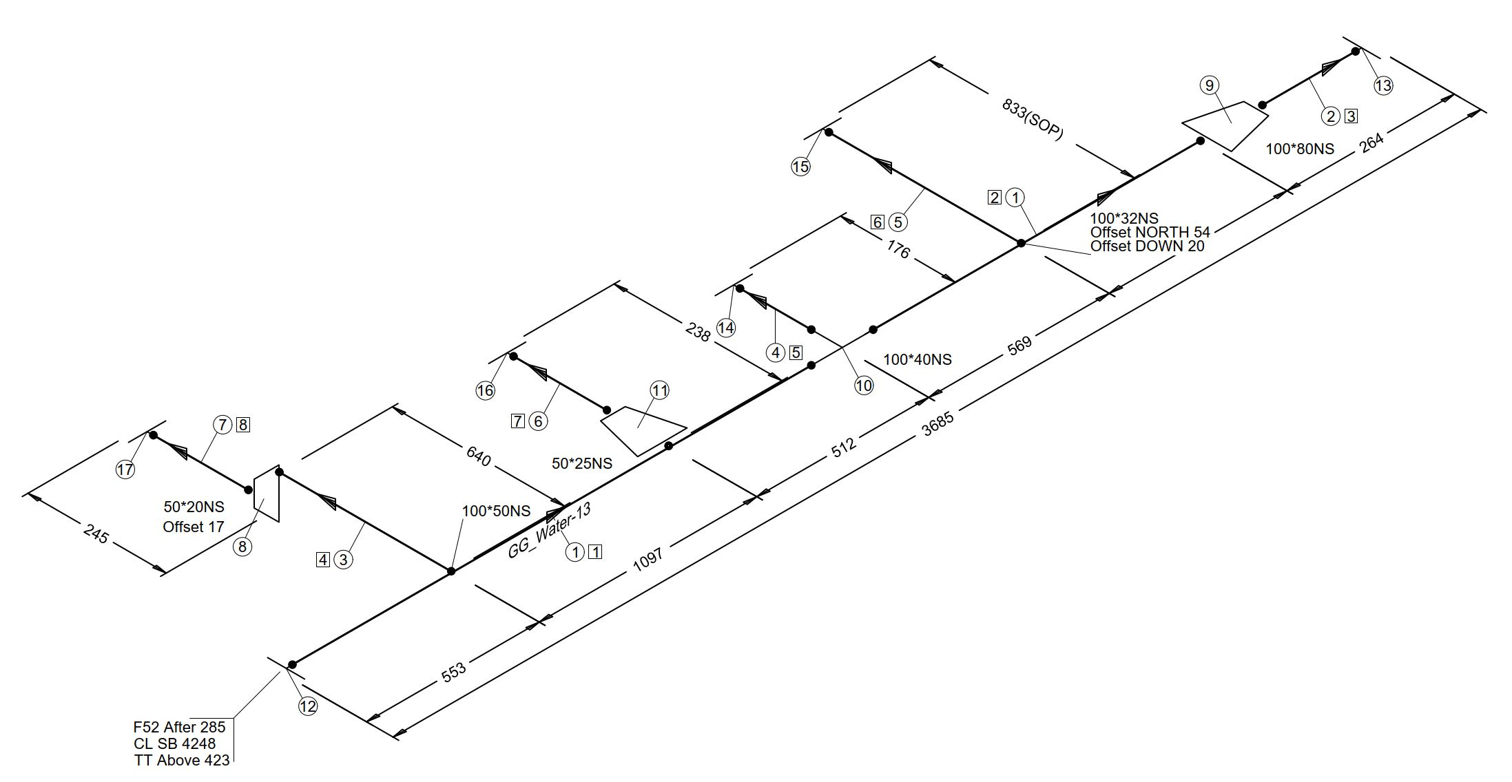
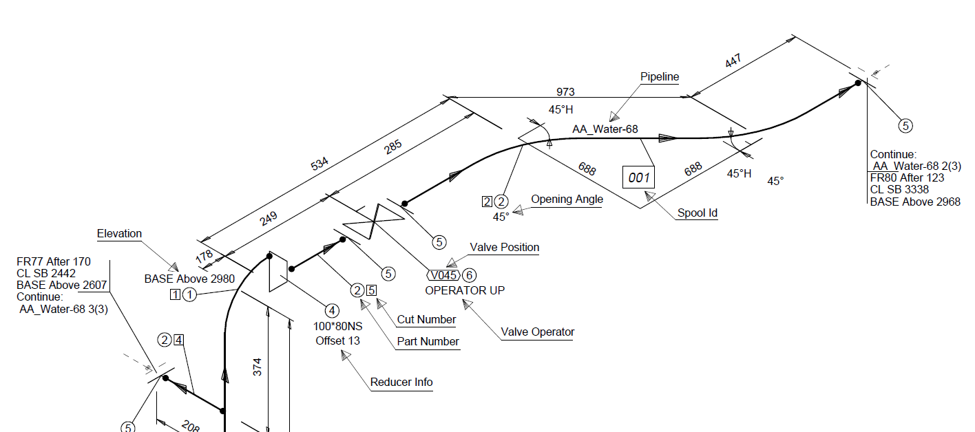
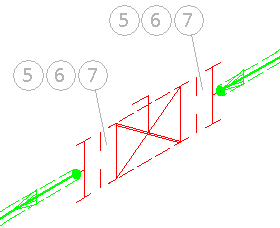
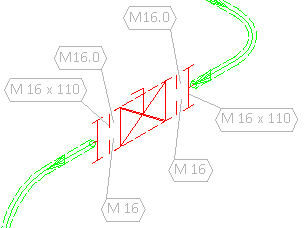
The project administrator can define what kind of annotations the automatic annotation tool should insert into isometric and/or pipe spool drawings. The picture below shows some examples of annotations that automatic annotation has inserted into an isometric drawing.
Automatic Annotation Settings
The Automatic Annotation Settings dialog has three tabs. If these settings are changed during the project, automatic annotation must be re-run in all documents to replace the existing annotations with new ones.
Main entities | Other labels | General
Main entities
On the Main entities tab, you can configure the following settings for isometric and/or spool drawings. The available options depend on whether you are defining settings for documents that are created in Piping Isometrics & Spools or documents that are created in Plant Modeller.
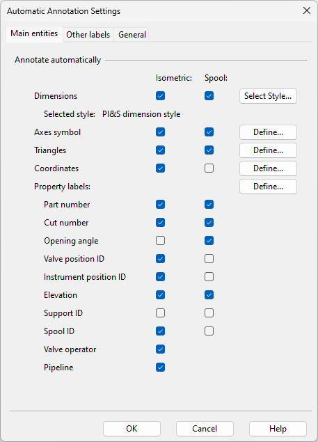
Dimensions | Axes Symbol | Triangles | Coordinates | Property labels
Dimensions
Select this option to allow automatic annotation to insert dimensions into drawings.
Clicking Select Style opens a dialog for selecting which Isometric Dimension Style to use for the dimensions.
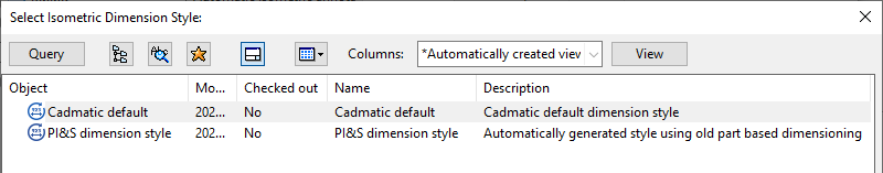
-
'Cadmatic default' is the default style used by isometrics created in Plant Modeller.
-
'PI&S dimension style' is the default style used by isometrics created in Piping Isometrics & Spools.
Axes Symbol
Select this option to allow automatic annotation to insert the axes symbol into drawings.
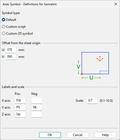
Clicking Define opens the Axes Symbol dialog where you can define the following settings.
-
Label type – Select whether to use the default axes symbol, a symbol defined in a custom script (PiAxesSymbol.mac), or a custom 2D symbol (pip_axes).
-
Offset from the sheet origin – Define the offset from the sheet origin (default symbol, custom script) or from the top-right corner of the drawing area (custom 2D symbol).
Note: If the specified location would cause the symbol to collide with lines within the drawing area, the program tries to find a more suitable location for the symbol.
-
Labels and scale – Define the labels to show for the positive and negative direction of each axis and the scale of the symbol. (Not applicable if using custom 2D symbol.)
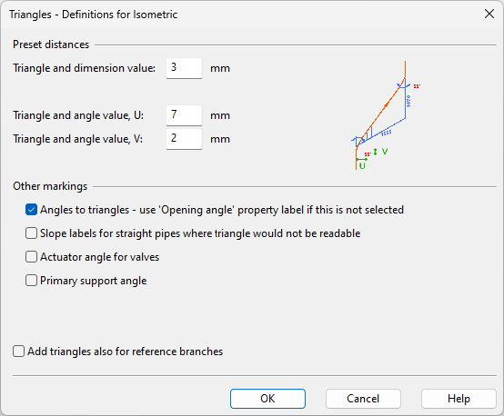
Triangles
Select this option to allow automatic annotation to insert triangles into drawings.
Clicking Define opens the Triangles dialog where you can define the following settings.
-
Triangle and dimension value [mm] – Specify the distance the between triangle and the dimension value.
-
Triangle and angle value [mm] – Specify the distance between the triangle and the angle markings.
-
Angles to triangles - use 'Opening angle' property label if this is not selected
-
Slope labels for straight pipes where triangle would not be readable – Adds a slope mark to sloping pipes.
-
Actuator angle for valves – Adds the actuator insertion angle to valves.
-
Primary support angle – Adds the insertion angle to primary supports.
-
Add triangles also for reference branches – Adds triangles to reference branches.
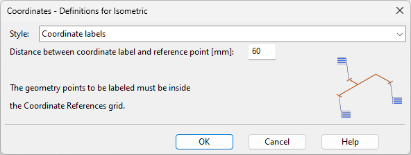
Coordinates
Select this option to allow automatic annotation to insert coordinate labels into drawings.
Clicking Define opens the Coordinates dialog where you can define the following settings.
-
Style – Select the style of coordinate labels:
-
Coordinate labels
-
Line coordinates
-
Coordinate labels for main run, nothing for other endpoints
-
Line coordinates for main run, coordinate labels for other endpoints
-
Line coordinates for main run, nothing for other endpoints
-
Both coordinate labels and line coordinates for main run, coordinate labels for other endpoints
-
-
Distance between coordinate label and reference point [mm] – Specify the distance between a label and the referenced geometry point.
-
Values to show in line coordinates – Select which coordinates to show when Style is set to display line coordinates: X, Y, Z
For both label types, a geometry point to be labeled must be inside the grid area defined by the Coordinate references configuration, or the coordinate value is not shown in the label.
Property labels
Select which of the following property labels automatic annotation can insert into drawings. Clicking Define opens label type specific settings.
- Part number
- Cut number
- Opening angle
- Valve position ID
- Instrument position ID
- Elevation
- Support ID
- Spool ID
- Valve operator (only available for isometrics)
- Pipeline (only available for isometrics)
- Assembly point (only available for pipe spool drawings)
Property label settings
On the Main entities tab, in the Property labels section, clicking Define opens the Property Labels dialog where you can define what kind of property labels automatic annotation should insert into drawings.
Cut and part numbers | Position IDs | Elevation and opening angle | Other
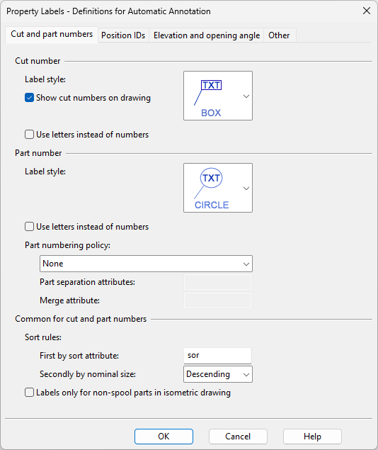
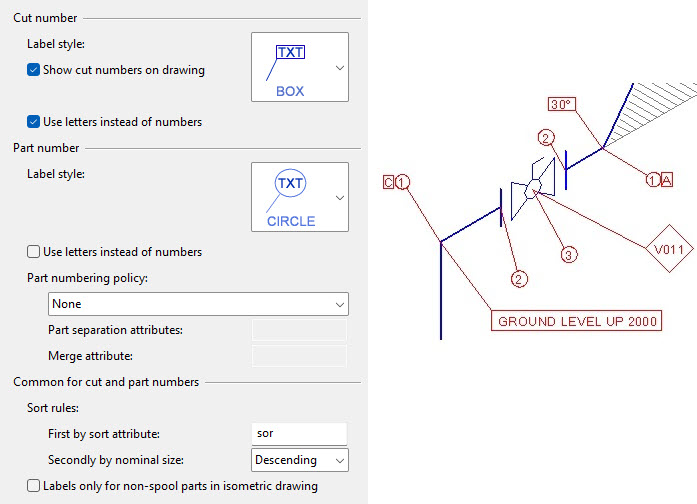
Cut and part numbers
On this tab you can define the following settings.
-
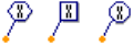
Label style – Select the visual appearance of the label.
-
Show cut numbers on drawing – Select this option to show cut numbers in drawings.
-
Use letters instead of numbers – Select this option to use letters instead of numbers. The range is A–ZZ (1–702).
-
Label style – Select the visual appearance of the label.
-
Use letters instead of numbers – Select this option to use letters instead of numbers. The range is A–ZZ (1–702).
-
Part numbering policy – Select whether the part numbering should use tag values to separate parts that have the same Part ID (pid) or merge parts that have different Part IDs.
-
None – Use the original part numbers in drawings.
-
Use part separation attribute & merge attribute – If selected, specify whether to separate and/or merge parts based on attribute values.
Part separation attributes – Enter a semi-colon separated list of the attribute tags (tag1; tag2; …) to use for assigning unique part numbers to parts that have identical Part IDs but different attribute values. When using this approach, all the parts should have all the designated attributes.
Merge attribute – Enter the attribute tag to use to assign a single part number to all the parts that have different Part IDs but the same attribute value (and same Nominal Size).
-
All parts get different part number – All parts that have identical Part IDs are given new, unique part numbers.
-
Common for cut and part numbers
-
Sort rules – You can set cut numbers and part numbers to be sorted primarily by attribute values (specify the attribute tag) and secondarily by nominal size.
-
Labels only for non-spool parts in isometric drawing – Select this option if automatic annotation of isometric drawings should only add part number and cut number labels to parts that do not belong to a pipe spool.
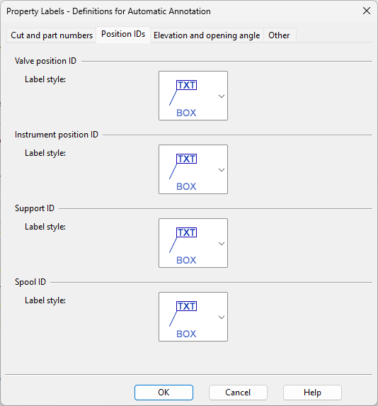
Position IDs
On this tab you can select the visual appearance of Valve position ID, Instrument position ID, Support ID, and Spool ID labels.
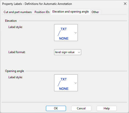
Elevation and opening angle
On this tab you can select the visual appearance of labels that show elevation or opening angle. For elevation you can also select the order in which the label shows 'level', 'sign', and 'value'.
Other
On this tab you can specify the following settings.
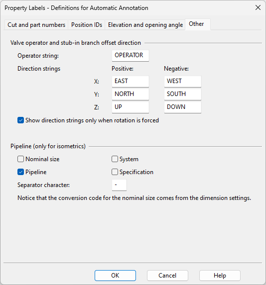
Valve operator and stub-in branch offset direction
- Operator string – Enter the text to show in labels that indicate the direction of an operating device (such as spindle, lever, or hand-wheel in a valve) or an eccentric stub-in branch.
- Direction strings – Enter the text to show for a given direction. Use direction names that are suitable in the given design context.
- Show direction strings only when rotation is forced – If selected, the direction string is shown only when the direction cannot otherwise be deduced. Clear the option to show the direction string in all cases.
Specify which of the following information to show for pipelines in isometric drawings:
- Nominal size (uses the conversion code defined in dimension settings—see Dimensions & Coordinates)
- Pipeline
- System
- Specification
Separator character – Specify the separator character to use for separating consecutive pieces of information.
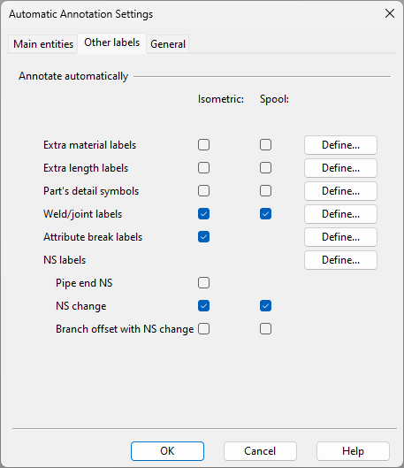
Other labels
On the Other labels tab of Automatic Annotation Settings, you can configure the displaying of different types of labels and symbols.
Extra material labels | Extra length labels | Part's detail symbols | Weld labels | Attribute break labels | NS labels
Extra material labels
Select this option to allow automatic annotation to insert labels for extra materials (bolts, washers, nuts) into drawings.
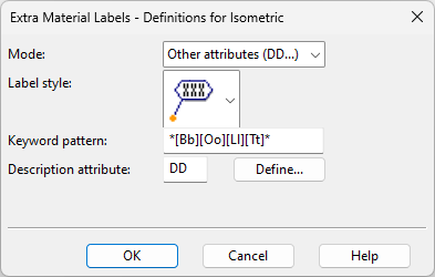
Clicking Define opens the Extra Material Labels dialog where you can define the following settings.
-
Mode
-
Part number – Select this option to display the part numbers of the extra materials in the label. The look of the label is defined in Part number settings, so automatic annotation must also be set to generate part numbers.
-
Other attributes (DD...) – Select this option to display the value of a specific tag in the label, using the following settings. Only extra materials that have a 'Geometry point index' (gep) tag can be labeled.
-
-
Label style – Select the label style to use.
-
Keyword pattern – Define a pattern for selecting the extra material based on a keyword. Examples:
Keyword pattern
Description
*
Labels all extra materials regardless of their keyword
[Bb][Oo][Ll][Tt]*
Only labels the extra materials that have a matching keyword, such as BOLT*
-
Description attribute – Click Define to select the extra material tag whose value to display in the label, such as 'Dimensional description' (DD).
Extra length labels
Select this option to allow automatic annotation to insert labels for extra length into drawings.
Clicking Define opens the Extra Length Labels dialog where you can define the following settings.

-
Label style – Select the label style to use.
-
Prefix – You can enter a prefix for the label text.
-
Suffix – You can enter a suffix for the label text.
The labels use the text height and conversion code defined for dimensions in Dimensions & Coordinates.
Part's detail symbols
Select this option to allow automatic annotation to insert a detail symbol for a part that has a symbol defined in the 'Detail symbol in isometric drawing' (Ids) attribute of the Catalog Part.
Clicking Define opens the Part's Detail Symbols dialog where you can define the following settings.
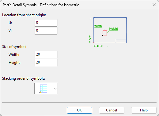
-
Location from sheet origin – Define the location of the symbol as offset from the sheet origin.
-
Size of symbol – Define the width and the height of the symbol.
-
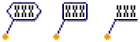
Stacking order of symbols – If more than one part in the drawing has the attribute, the symbols are inserted into a grid, and you can select the direction in which the grid grows:
-
 – First symbol is in the lower-left corner, grid grows upward.
 -
 – First symbol is in the upper-left corner, grid grows downward.
-
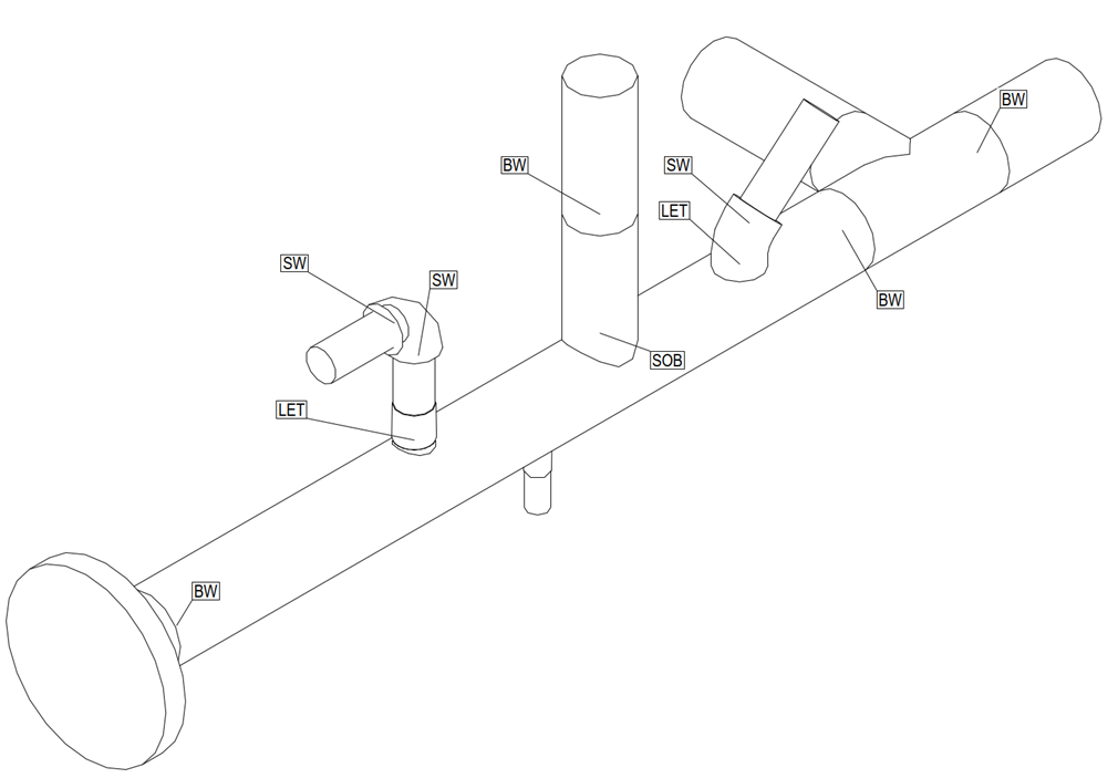
Weld labels
Select this option to allow automatic annotation to insert labels for welds in drawings. The joint information is available in the Weld File (see Queries) and it can be added to the drawing sheet as a table.
The available options depend on the application you are using.
-
In Plant Modeller, clicking Define opens the Weld Labels dialog with the following settings.
 Show/hide details
-
Label style – Select the label style to use.
-
Weld ID prefix – You can set a specific prefix to be added to weld IDs.
-
-
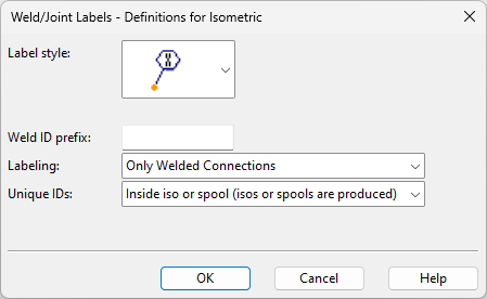
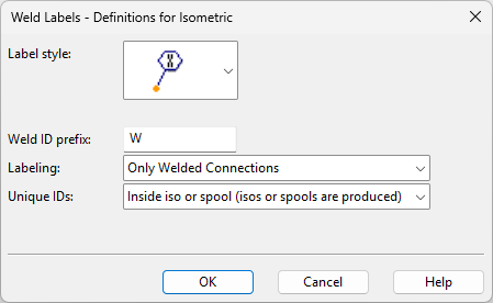
In Piping Isometrics & Spools, clicking Define opens the Weld Labels dialog with the following settings.
Show/hide details
-
Label style – Select the label style to use.
-
Weld ID prefix – You can set a specific prefix to be added to weld IDs.
-
Labeling – Select what to label:
-
Only Welded Connections – Weld numbers are generated for welded joints.
-
All Type of Connections – Weld numbers are generated for all joint types.
Note: If joint information is wanted also for onto-line parts such as sleeves with no cut, the setting must be 'All Type of Connections' and the Catalog Part keyword must be WELD.
-
-
Unique IDs – Select how to assign IDs to isometrics and spools:
-
Inside iso or spool (isos or spools are produced)
-
Inside iso (both isos and spools are produced)
-
Inside spool (only isos are produced)
-
-
To make the information visible in an isometric or spool document, the weld table must be defined in the ICGD and in the drawing sheet.
Example weld table in a drawing sheet:
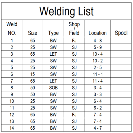
Columns of the weld table:
-
Weld NO. – Unique weld number inside isometric or spool document.
-
Size – Nominal size of welded part or branch part.
-
Type
-
'LET' Outlet with Standard Component with branch connection
-
'LET' Outlet made with route pipe add part
-
'SOB' Stub-in branch
-
'SW' Female socket
-
'BW” Butt-weld
-
'BW' Pipe end
-
'SOF' Welded connection of slip-on flanges
-
-
Shop / Field
-
'SJ' Shop weld
-
'FJ' Field weld
-
-
Location – Part numbers of the welded parts.
-
Spool – Number of the spool that contains the weld. If the weld is on the border of two spools, then the number of the second spool is shown.
Data that weld tables in the drawing sheet can use:
-
Document header data:
-
nam Isoname;
-
spn SpoolName;
-
nop NumberOfPoints;
-
now NumberOfWelds;
-
nnw NextNewWeldId;
-
-
Attributes (material tags):
Tag*
Description
Example Data
wID
Weld number
6
wTY
Coded Joint Type
0
wSF
Shop or Field weld
SJ or FJ
wCT Weld Type BW, SW, LET, SOB or SOF wFP (wSP)
1st (2nd) part's part ID
+FuBIf68THrcv4tXmJie7pW-34
wFO (wSO)
1st (2nd) part's model object ID
CvgenFsZHMYr7F8wCVlAUm
wFC (wSC)
1st (2nd) part's connection code
9C
wFD (wSC)
1st (2nd) part's dimension description
DN2 1/2" x DN1/2"
wFN (wSN)
1st (2nd) part's nominal size
15.00
wF$ (wS$)
1st (2nd) part's alt. nominal size
1/2";
wFM (wSM)
1st (2nd) part's material
ASTM A 105
spn
Spool number
2
pn1 (pn2)
1st (2nd) part's part number
11
Gep
Point index in drawing
26
* Tags inside parentheses are for the second part.
Example isometric document:
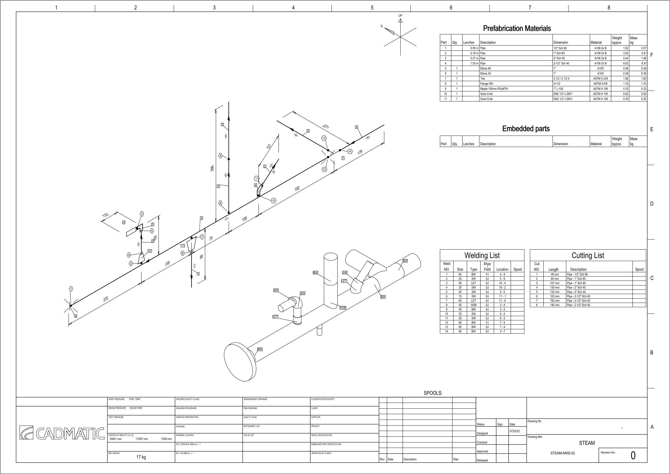
In the CADMATIC example project, the 'Cadmatic_spool' drawing sheet and ICGD have a weld table.
For more information on material tags, see Material attributes.
Attribute break labels
Select this option to allow automatic annotation to insert a label to those locations where the value of a specific attribute changes.
Clicking Define opens the Attribute Break Labels dialog where you can define the following settings.
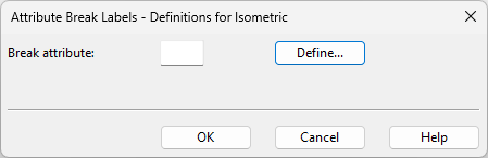
-
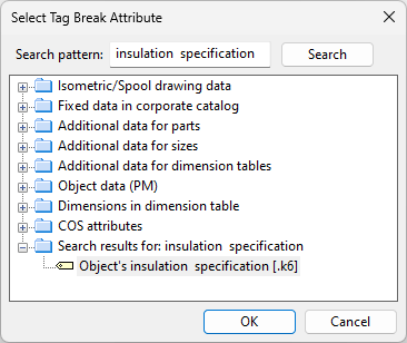
Break attribute – Enter the tag of the attribute to use, or click Define to search for the tag.
NS labels
You can select these options to allow automatic annotation to insert a nominal size label to pipe ends, to those locations where the nominal size of the pipeline changes, and to also show the branch offset if the change occurs between a main pipe and an eccentric branch.
-
Pipe NS – Select this option enable the insertion of nominal size labels to pipe ends.
-
NS change – Select this option to enable the insertion of nominal size change labels.
-
Branch offset with NS change – Select this option to enable the insertion of nominal size change labels that also show the offset of an eccentric branch from the main axis. The offset direction strings can be customized in Property labels > Other > Valve operator and stub-in branch offset direction.
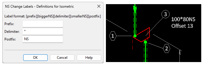
Clicking Define opens the NS Change Labels dialog where you can define the following settings.
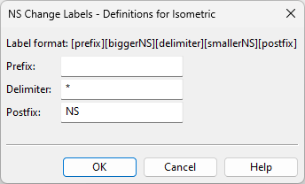
-
Prefix – You can enter a prefix for the label text, up to 19 characters.
-
Delimiter – You can enter a delimiter to be inserted between the NS values, up to 19 characters.
-
Postfix – You can enter a postfix for the label text, up to 19 characters.
In this example, an eccentric reducer changes the nominal size from 100 to 80 and offsets the pipeline by 13 mm.
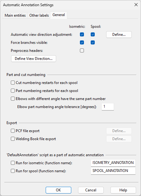
General
On the General tab, you can configure miscellaneous automatic annotation settings.
-
Automatic view direction adjustment – Select this option and click Define if you want to specify an adjustment angle for the annotation of isometrics or spools.
-
Force branches visible – Select this option to enable short branches to be slightly rotated in cases where they would be hidden by the main pipe.
-
Preprocess headers – See Preprocess headers filter.
-
Define View Direction – Opens a dialog for defining the view direction of the annotations.
Part and cut numbering
-
Cut numbering restarts for each spool – Select this option to restart cut numbering for each spool.
-
Part numbering restarts for each spool – Select this option to restart part numbering for each spool.
-
Elbows with different angle have the same part number – Select this option to use the same part number for elbows regardless of their angle, and the specify the angle value to use for considering whether the angle is different.
-
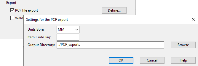
PCF file export – Piping Component File (PCF) export allows CADMATIC to interface with the ISOGEN® system by exporting component and routing information to a text file. For more information, see PCF Export.
'DefaultAnnotation' script as a part of automatic annotation
You can enable the use of the script [project] > Resources > Scripts > DefaultAnnotation to add additional annotations to isometric drawings and/or spool drawings.
-
Run for isometric (function name) – If enabled, specifies the name of the macro to run when annotating isometric drawings.
-
Run for spool (function name) – If enabled, specifies the name of the macro to run when annotating spool drawings.